Feeds:
Posts
Comments

Posts Tagged ‘Arduino’

Geek Sunday

Imagine that it’s a Sunday morning, and you are pretty bored and want to do something relaxing and a little bit of fun. Imagine that you talked about LEDs and Arduinos with a colleague two days before, and so you have checked your electronics storage and know perfectly how many LEDs you still have (too many, I can assure you). Why not do something fun with them? For example, LEDs that play along a MIDI track 🙂

So, what I did was:

  1. find out a nice MIDI track, a not too complex one if possible; I decided for “Twenty One” by Jessica Curry, from the “Dear Esther” soundtrack: I love that theme, and it’s basically a single instrument (a piano). I already had a MIDI version of it, which I simplified a little bit (I basically removed the counter-theme)
  2. find out how many 220 Ω resistors you have (turns out: about 40, that go along perfectly with the 36+ red LEDs that I had)
  3. find out how many shift registers (the famous 595 IC) you have: not so many, unfortunately. I only had 3, so I can pilot up to 24 LEDs, or 2 octaves. I would have preferred 3 octaves…

I put together the circuit (I tried to resemble a piano keyboard, with two rows of “keys”; if I had more LEDs of a different color, the result would have been better. Also, I didn’t want to solder anything, so the positioning on the breadboard cannot be as precise as one would like. I also needed two more LEDs, that I had to switch on and off from the Arduino side without the 595) and the code: it uses the MIDI library to receive the “note on/off” messages from the serial line (you can see the RX LED switching on the Arduino in the video), and it switches the LEDs according to the pitches that it receives. Since I only had 2 octaves, I had to transpose the theme one octave down, and since the MIDI file had 3 tracks but I had just one line of LEDs, I had to prioritize the tracks: basically, if the same note is played by two tracks, the track with the highest priority would decide when to stop the note. I achieved this by reordering the tracks in the MIDI file, so that the ones with a highest channel number have a highest priority.

The last step from the Arduino point of view was install the dear old Hiduino firmware: basically it allows the Arduino to be recognized as a MIDI device, instead of a serial device, so that it can communicate with multimedia apps on the computer side. Of course, once you rewrite the firmware, you need to upload the sketches from the ISP header.

Finally, I fired up Jack (the low latency audio daemon), Rosegarden (to reproduce the MIDI file) and KMidiMon (to monitor the MIDI events), I connected the Arduino to the computer, routed the MIDI lines to all the “clients”, and voilà!

This slideshow requires JavaScript.

P.S.: nevermind the names of some of the variables in the code: they come from previous experiments with the 595s, and I haven’t changed them due to laziness…

Read Full Post »

A few weeks ago I ported the Firmata library to Lua, as a first step of an experiment of a DIY Arduino Yun. For several reasons I had to postpone that experiment (reasons being writing my Ph.D. thesis, and the fact that the Carambola board has the wrong pin distance to do anything good with it), and now I have an Arduino Yun, which essentially is a Carambola done well (and I couldn’t expect less by the Arduino people).

So, the next step is to run my Erlang framework, ELIoT, on it (the fact that the Yun has double the internal flash memory of the Carambola and support for external SD cards is simply great), and to interact with the microcontroller (the usual Atmega 32u4) I needed a porting of Firmata to Erlang. The Yun team gives you a Python library for intercommunication, but since it is not C/C++ I couldn’t make a wrapper to an Erlang driver, so I decided to go (Erlang) native.

Thus, meet the library: as before, it is a simple port of the Java Processing one, meaning that it supports only analog and digital write/read operations, among the other operations of Firmata. I have tested it on the Arduino Yun: the Atmega 32u4 was running the Standard Firmata sketch, and a computer was running Erlang and the library (I still have to install Erlang on the Yun microprocessor itself), and it works, at least with the usual simple test of enabling the integrated LED and read from one of the analog sensors.

The library itself is structured as a gen_server: just one instance each time, of course.

*** UPDATE ***

Now the library works in both push and pull modes: a client can query the server to obtain the current values of sensors, or it can receive the updates directly from the server by subscribing to a specific (analog or digital) pin.

Beware that the latter will generate a new update message for each Firmata update from the Arduino (for example, the StandardFirmata sketch running on my Yun produces about 50 messages per second, one update every 20 ms). You may need to filter these messages, e.g., taking action when a certain threshold between consecutive values is exceeded.

Read Full Post »

Arduino in a box

Arduino in a box

Un paio di righe per descrivere brevemente un esperimento preparato stamattina con Arduino ed un paio di accessori.

Il problema è il seguente: capita di andare via di casa per diversi giorni (ad esempio a Natale o ad agosto), per vacanza o per altri motivi; al vostro ritorno, potreste domandarvi se è mancata o meno la corrente, e di conseguenza se quanto avevate lasciato in frigorifero o in freezer è ancora commestibile. Nel mio caso, so se è mancata perchè la sveglia del comodino lampeggia, ma non ho idea del tempo in cui sia effettivamente mancata.

Da qui, l’idea di mettere assieme un Arduino, un RTC ed uno shield con SD, per scoprire effettivamente se e per quanto tempo sia mancata la corrente quando non sono in casa. Il codice sotto riportato scrive su un file una riga di timestamp ogni 5 minuti (sfruttando l’interrupt che l’RTC lancia una volta al minuto): se la corrente viene tolta, l’Arduino si spegne e smette di scrivere su file, salvo poi riprendere al ripristino dell’alimentazione, e l’RTC avrà mantenuto nel frattempo l’orario (essendo alimentato a batteria), ed una semplice analisi del contenuto del file permetterà di scoprire l’intervallo di tempo in cui non sono stati scritti timestamp.

Non do rassicurazioni sul codice sotto riportato: test brevi hanno funzionato, ma sto ancora svolgendo un test prolungato nel tempo. L’unica particolarità del codice è che sia l’RTC che la SD comunicano attraverso SPI, utilizzando due modalità diverse (MODE3 vs. MODE0), quindi bisogna alternare le due prima di usare l’uno o l’altro dispositivo. La libreria per RTC serve solamente a semplificare la scrittura nei registri, mentre la libreria Time serve per tradurre una data ed ora in UNIX timestamp.

I collegamenti hardware dell’RTC sono molto semplici e vanno sulle connessioni standard SPI dell’Arduino Uno (CS è 10, dato che lo shield SD ha CS sul pin 8); l’uscita SQW dell’interrupt del DS3234 va al pin 2, che corrisponde ad interrupt zero per l’Arduino Uno.

#include <SPI.h>
#include <ds3234.h>
#include <SD.h>
#include <Time.h>

#define RTC_CS 10
#define SD_CS 8
#define RTC_INT 2
#define MINUTES 5
#define FNAME "logger.txt"

int time_interrupt = MINUTES;
File logger;

void setup()
{
  Serial.begin(115200);
  pinMode(RTC_INT, INPUT);
  pinMode(SD_CS, OUTPUT);
  SPI.setDataMode(SPI_MODE3);
  DS3234_init(RTC_CS, DS3234_INTCN);
  DS3234_clear_a2f(RTC_CS);
  set_next_alarm();
  SPI.setDataMode(SPI_MODE0);
  attachInterrupt(0, INT0_ISR, LOW);
  SD.begin(SD_CS);
  Serial.println("Waiting for first alarm...");
}

void loop()
{
  struct ts t;
  tmElements_t t2;
  time_t time;

  if (time_interrupt == 0) {
    SPI.setDataMode(SPI_MODE3);
    DS3234_get(RTC_CS, &t);
    SPI.setDataMode(SPI_MODE0);
    t2.Second = t.sec;
    t2.Minute = t.min;
    t2.Hour = t.hour;
    t2.Wday = t.wday;
    t2.Day = t.mday;
    t2.Month = t.mon;
    t2.Year = t.year - 1970;
    time = makeTime(t2);
    logger = SD.open(FNAME, FILE_WRITE);
    if (logger) {
      logger.seek(logger.size());
      logger.println(time);
      logger.close();
    }
    time_interrupt = MINUTES;
  }
}

void set_next_alarm(void)
{
  SPI.setDataMode(SPI_MODE3);
  boolean flags[4] = { 1, 1, 1, 0 };
  DS3234_set_a2(RTC_CS, 0, 0, 0, flags);
  DS3234_set_creg(RTC_CS, DS3234_INTCN | DS3234_A2IE);
  SPI.setDataMode(SPI_MODE0);
}

void INT0_ISR(void)
{
  detachInterrupt(0);
  --time_interrupt;
  SPI.setDataMode(SPI_MODE3);
  DS3234_clear_a2f(RTC_CS);
  SPI.setDataMode(SPI_MODE0);
  attachInterrupt(0, INT0_ISR, LOW);
}

Read Full Post »

image

L’immagine qui sopra è tratta dal datasheet che potete trovare sul sito della board; la riporto qui perché trovo sia interessante il fatto che, rispetto a tanta concorrenza (da Arduino Yun a pcDuino), qui l’interfaccia hardware Arduino-compatibile è fornita direttamente dal chip, e non da un microcontrollore a parte.

Da un lato, temo che così si perda la parte real-time che il microcontrollore permette di raggiungere, dall’altro però accedere all’interfaccia hardware (e magari anche all’API software di Arduino) dovrebbe essere possibile senza librerie intermedie (tipo la Bridge per lo Yun). Mi interessa semplicemente per pensare di costruirne un wrapper in altri linguaggi (chessò, Erlang per dire…).

Spero di riuscire ad aprire presto l’immagine Linux che viene fornita con la board, così da capire che librerie ci sono e cosa ci si può linkare (l’architettura è .586).

Read Full Post »

Saluti da Roma!

Sto seguendo la MakerFaire edizione europea, organizzata da Riccardo Luna e Massimo Banzi qui al centro congressi dell’EUR. Oggi c’è stata la conferenza d’apertura, decisamente interessante e con un sacco di ospiti che finalmente si sono potuti conoscere di persona (dagli organizzatori, a gente come Dale Dougherty, Bruce Sterling e tanti altri).

image

Inutile dire che il clou della giornata è stato il breve panel con il CEO di Intel, che ha annunciato la volontà dell’azienda di entrare nel mondo dei makers, mondo che avevano (colpevolmente) ignorato finora, e per farlo hanno iniziato una partnership con Arduino ed annunciato (e distribuito ai partecipanti 😀 😀 😀 ) il primo Arduino Intel-based (e dicono di averne un altro paio in canna). Il tutto in pieno spirito open hardware, con quindi tutta la parte elettronica aperta (stanno cercando i canali giusti di distribuzione, dato che quelli che hanno sempre avuto finora trattavano partner industriali e quantità molto grosse; la distribuzione della board inizierà a novembre). Sul lato software, appena provo il tutto scriverò in proposito (no, non so manco le specifiche hardware: oggi sono stato impegnato fino a tardi, ed ora ho l’unico accesso alla WiFi dell’albergo in uso per backup delle foto, appena finisce andrò sul sito a vedere (suspense); posso dirvi che c’è un attacco che non conosco, ed oggi si ventilava l’ipotesi pci-express… E l’alimentatore è da 2 A).

Ora, eccitazione a manetta a parte, e detto che non ho ancora provato nulla (ho solo aperto la scatola e scoperto che tra le altre cose hanno installato un altoparlantino che suona il jingle di Intel quando ribalti la scatola -_- ), propongo la seguente riflessione: da un lato l’arrivo delle grandi aziende è indice secondo me di diverse cose, dal fatto che il movimento dei makers è qui per restare al fatto che Intel potrebbe far saltare il banco in un campo che era preda di altri produttori di hardware, al fatto che Intel, da sempre distributrice di ad es. driver open per PC, promette schematiche altrettanto open.

La mia domanda è: l’ingresso di una realtà così grossa cosa significa per le tante realtà più piccole? I mean, durante il panel si diceva che la collaborazione in oggetto è iniziata 2 mesi fa, ed Intel in quattro e quattr’otto ha messo in campo l’expertise del caso e prodotto una scheda funzionante in fase di distribuzione. Per dire che, se ci sono le competenze, la concorrenza non è banale. Più che altro, mi viene in mente il paragone con la figura della Disney nel romanzo “Makers” di Cory Doctorow…

Read Full Post »

Carambola and Arduino

Carambola and Arduino

The makers world, or at least myself, is waiting for September 10th, when Arduino will start selling a new product, the Arduino Yun: it’s an interesting event, because it’s been a few months since several other (for a lack of a better word) IoT devices producers have started developing and selling similar devices (e.g., pcDuino), combining microcontrollers and microprocessors in a single, embedded board, and I (for one) want to see what the Arduino company has to offer in this field.

The main idea behind these devices is that you can use microcontrollers for some tasks, in particular for interfacing with hardware through GPIO, PWM (which is not often found in microprocessor boards) and others, with a (soft) real time approach, while the microprocessor often includes a WiFi (and Ethernet) chip, and runs an operating system like Linux (or variants such as OpenWRT), thus is more apt to handle network communication with the Internet and online services. I have to admit that at the beginning I thought it didn’t make a lot of sense: if you needed a microcontroller, you could use a microcontroller, and if you needed a microprocessor, you could use one. But then the idea of having both on the same board, with good libraries for data exchange between the two, started to make sense (needless to say, I already have in mind a couple of projects, but no spoilers yet).

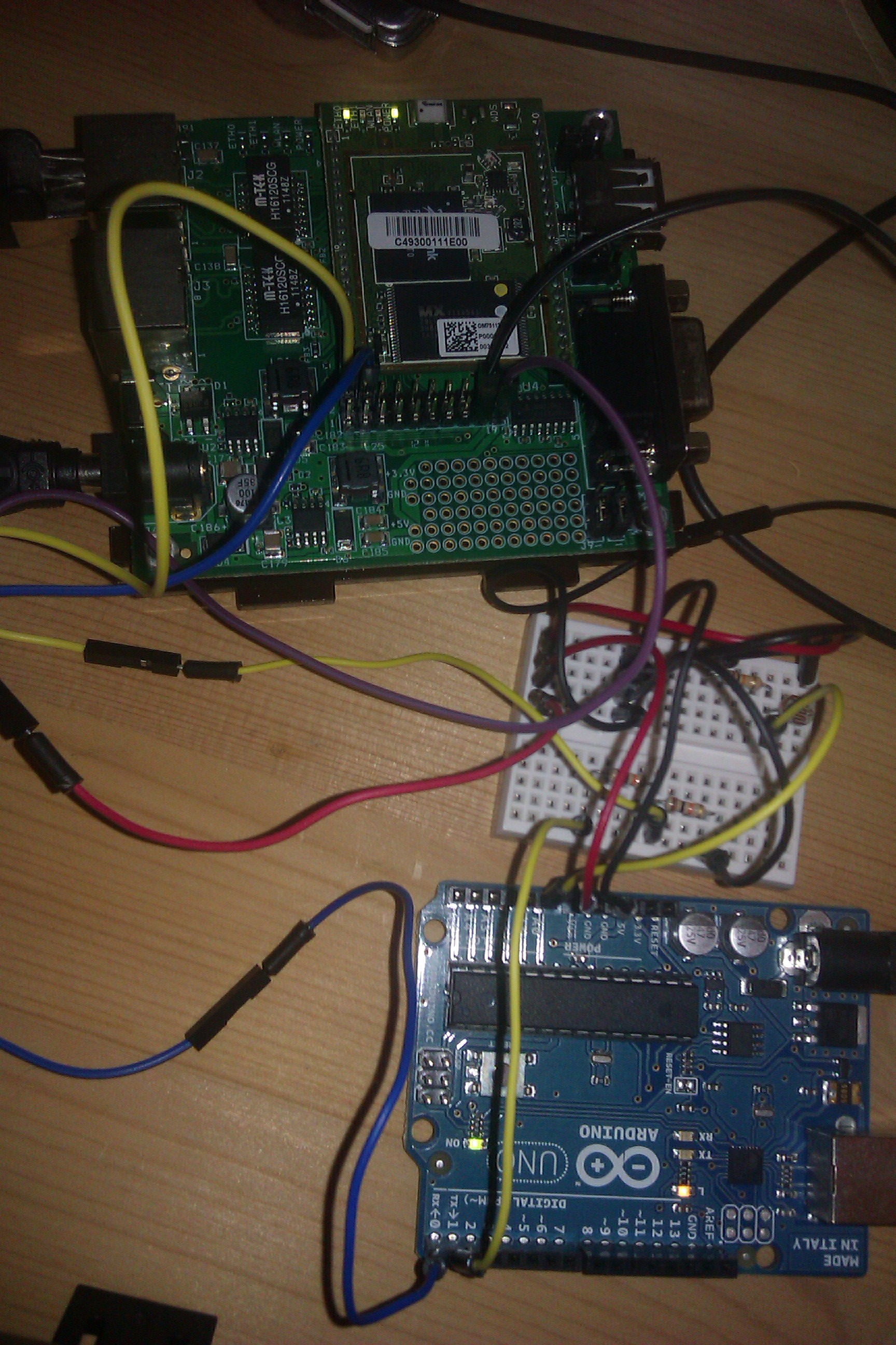
That said, while waiting for September 10th, I tought it could be interesting to make my own “Arduino Yun”, to combine a router-like device running OpenWRT with a microcontroller. What you can see in the photo above is the first step in this direction: hardware connections and software libraries.

The hardware

The OpenWRT board is a Carambola, about which I already wrote several posts in the past couple of years: it is a MIPS board with 32 MB of RAM and 8 (!) MB of Flash disk, plus several I/O pins (but no PWM), two Ethernet ports and a WiFi chip; in the photo it is shown with its dev board (the Carambola itself is the smaller piece with the two leds in the upper part of the photo). The microcontroller board is simply an Arduino Uno (rev2).

The Carambola (with the dev board) is powered by a 12V supply, and in turn it powers the Arduino through the Vin pin; the two communicate through one of the two UART ports of the Carambola, in particular the one “exported” on the pins (ttyS0; ttyS1, the other one, is connected on the dev board to a DE-9 connector). A voltage divider is needed, because the Carambola pins run at 3.3V, while Arduino ones run at 5V, so you cannot connect directly the Tx pin of the Arduino to the Rx pin of the Carambola (while the other direction works: 3.3V is enough for the “high” state of Arduino pins).

The small breadboard also contains a photoresistor, connected to the first analog input of the Arduino, and the reason why it is there will be explained in the next section.

The software

The Arduino people have developed a new library for the Arduino Yun (called “Bridge”), but in my experiment I wanted to use something already existent, so my first thought was Firmata. I used it in the last couple of experiments to interface Arduino with Processing (Java, basically), and I thought I could do the same here.

So, Arduino Uno is running the latest Firmata library (the one distributed with Arduino IDE 1.0.5); at this point, I had to find the corresponding library to run on the Carambola board. Now, on OpenWRT, with only 8 MB of Flash, it is really hard to make space to languages or other not-so-small applications, so the first choice would have been C: I’m pretty sure there is a Firmata library for C/C++ somewhere (I didn’t search for it, but nevertheless…), but I thought it would be less difficult to use other languages (especially because I would like to implement something a little more complicated that the example that I’m showing here).

Now, the language with the smallest footprint I think is Lua (there is also the choice of “Python mini”, but I didn’t try it), so I recompiled OpenWRT with Lua and a serial library that I found on the Internet, and I installed everything. At this point, I only needed a Firmata port to Lua, which didn’t exist (there are a couple of posts on the Web of people saying that they needed it, but no code whatsoever). So I decided to write it down myself (without knowing the language: I met the creator of Lua at the LASER Summer School last year, but I never used it): if non-developers are able to use that language to write scripts for various applications, I should be able to write some hundreds lines of code!

So I ported the Java library (~300 lines of code including comments) to Lua (~200 lines of code), with the help of a couple of libraries for handling bitwise operations and scheduling coroutines (to be able to read and write on a serial port at the same time). I had to go past a couple of “peculiar” characteristics of Lua (e.g., counters in arrays start from 1, or the coroutine scheduling itself was pretty new to me), but everything seems to work correctly now.

The example application simply connects to Arduino (the serial port name may have to be changed depending on your devices), then switches the test led (pin 13) on and off every two seconds, while reading from the analog port values coming from the photoresistor (or any other analog sensor) when switching the led itself (photo below, the peak in the photoresistor values is due to the flash light of the camera). The other coroutine reads periodically from the serial port, if there are bytes waiting to be read. The code may not be the best one written in Lua, but I still don’t know all the peculiarities of the language so I had to improvise from time to time (and take inspiration from the Lua wiki). There is a line that needs to be changed, whether the code is running on a computer or on OpenWRT (because of different implementations of the gettimeofday posix call).

Photoresistor values

Photoresistor values

Limitations

The code works with the configuration described above; I have to admit that I had problems with older Arduino boards (e.g, with the Duemilanove running on ATMEGA 168, Firmata seems not to be working at all, also using Java on the computer side) and with the newest one (an Arduino Uno rev3 SMD, which seemed not to be working with Lua on the Carambola with serial communication through pins, while it worked if connected to the Carambola through USB, so maybe there is a catch with serial pins… I didn’t investigate the problem, I simply used a different Arduino Uno board that I had lying around).

The next steps

The next step is to remove the dev boards: this means remove the dev board from the Carambola and power it directly through its pins (and access it through WiFi with ssh), and take the ATMEGA 328P (the microcontroller from the Arduino Uno) alone (maybe with an external quartz oscillator, not sure about it because I could run it with the internal one, at 8 MHz instead of 16 MHz), program it with Arduino Firmata, and then connect it directly to the Carambola, again through its pins.

Stay tuned!

Read Full Post »

Lego crane

Lego crane

As I wrote earlier this month, I bought a LeapMotion device (during the pre-selling phase), and as it arrived I tried to find some way of playing with it, not only with the apps from its store, but with its API, in particular integrated with Processing.

After some experiments with movement detection, coloured boxes and whatnot, I decided to try something physical. I had a couple of servos lying around, and they too were still looking for some test application (I had never used them), so I decided to put everything together. I built a crane using some Legos (from my youth) that were in a box in my closet here in my parents’ house, adding the two servos even if they do not fit perfectly (but the connection of the servos was almost perfect with the Lego gears, so in the end it was not that bad). The crane has two degrees of freedom: the red platform rotates with a continuous servo, and the black arm goes up and down with a standard servo.

The Arduino has the Adafruit motor shield (the old version actually), and I uploaded a firmata sketch to send commands from Java (Processing) without having to come up with a specific protocol; on the computer side, a Processing sketch receives frames from the LeapMotion and detects two movements: the inclination of the palm of the hand (detected only if there are at least 4 fingers in view, this means that there should be some distance between the single fingers, otherwise it doesn’t work) and the circle gesture, that happens when a finger performs a circle clockwise or counterclockwise; the first movement raises the arm, the second movement moves the platform.

http://www.youtube.com/watch?v=8tiFtJSMCyc

The video shows it working: the palm movement is sometimes detected with some delay, I think because of the angle values of the palm inclination that I put in the sketch (also, sometimes the angles assume some strange values, completely different from the previous ones, I have no idea why…*). Anyhow, it was nice to write some really easy code to detect stuff with the LeapMotion and apply it to physical stuff (instead of virtual stuff, like the apps), even if it was a toy application.

* I have to add that Linux users, at least as of today, are still second-class citizens for the LeapMotion world: not only there are no apps (but I don’t really care about this), but the SDK has a quite low version number with respect to Windows and Mac OS X, even if the latest news update from LeapMotion devs says that the latest version of the SDK is coming to us as well. This may be the cause of some misdetection happening from time to time.

Read Full Post »

This slideshow requires JavaScript.

The idea behind this little experiment (and another one that I have in mind) is to include the physical world into the guitar effects chain: usually these effects simply act to an explicit interaction, the foot movement on a pedal, but why not include the guitar movements? This first experiment, in particular, uses an accelerometer to variate the output of a Wah pedal, depending on the inclination of the neck of the guitar itself.

Collect the informations

The first part of the circuit is all about getting data from the accelerometer and sending them to drive the effect. The accelerometer (a triple-axis model) is connected to a Telosb platform through a small prototipying board; the internal software (TinyOS, of course) samples the three ADCs (one for each axis) by mediating 10 consequent samples, packs the three 2-byte values into a packet and sends them through the radio. This operation is performed about 20 times per second. No radio power management is done here (I don’t really care about batteries to last only a few hours or days).

A second Telosb receives the radio packets. Now, the natural follow-up would be for the Telosb itself to drive a digital pot (through I2C, for example), but from this point of view the MSP430, the Telosb microcontroller, sucks A LOT: it has two multi-purpose hardware ports (called USART), each of them has a UART and a SPI interface, and one of them has also a I2C interface. One SPI is not connected in the board, while the other SPI and the I2C are already used by the radio, in the same port that has one UART (the other UART goes to a FTDI chip that sends data through the USB port). This means that driving the hardware port and communicating with the radio means having to share the resources and manage them so that only one is active at a time. I have to say that I was quite scared by this, first of all because TinyOS is not easy to be used to develop applications, and secondly because I am sending so many packets through the radio that I don’t know if timing was enough to start and stop each interface every time.

Thus, I decided to use an Arduino with an USB Host shield: in this way, the Telosb simply takes the radio packets and routes them to the usual USB serial port; the Arduino receives the data, unpackets the three accelerometer values, uses them in a moving average (to avoid too sudden movements) and puts the current value to a digital pot. In the end, I am using only one of the three axes (the X axis), and discarding the other two.

Colorsound Wah

Schematic view

Schematic view

I decided to use a wah pedal as the best effect to be driven by these movements, and I decided to use this schematic, with a couple of modifications; the interesting thing about this circuit is that an inductor, usually the essential part of a wah, is not needed: it just needs a transistor and several resistors and capacitors. The modifications are the two resistors R4 and R10, and the electrolytic capacitor and the diode on the power line on top (C1 and D1).

There are two different power supplies: 9V are provided by a battery, while the Arduino is powered separately and provides the 5V needed by the digital pot; this is done to avoid introducing noise to the effect, because the Arduino is also powering the Telosb radio.

Tests

The first tests have been made with a sketch on Processing showing a 3D box moving according to the accelerometer values; I have published several videos showing all these tests, with Arduino first and with the Telosb later. The final circuit is shown here (for some reasons the video is quite accelerated, I have no idea why but I think it involves the fact that all these videos are without an audio track, and Youtube does something wrong when loading them…), and I have added a brief video showing the result down here. The audio quality is quite low, I have recorded it with a microphone and not with an acquisition device, but for now it will suffice.

Final thoughts

I am not completely satisfied with the final result: trying a guitar effect on a breadboard is quite hard, because any movement of the wires introduces some noise, and it probably also lowers the effect of having capacitors in the circuit. I would try to move the circuit at least on a prototipying board, then lower the sampling timing again, from 50 ms to maybe 25-30 ms and see if the rest of the circuit is able to cope with it; also removing the Arduino and allowing the sink to directly drive the pot would lower the latency, but again the MSP430 makes it quite difficult (and I don’t have radio devices for the Arduinos, like for example the XBee shields). Bluetooth could be a solution to use a single platform (I already have a bluetooth shield for Arduino, and the USB Host supports some dongles). Also the moving average window could be reduced, to allow the effect to act quicker.

I think I will try also using a membrane like these instead of the accelerometer, to link the wah gain to the position of the left hand on the guitar neck (the membrane would be in the back of the neck), thus to the pitch of the music (higher pitch in general means the hand is nearer to the body of the guitar, lower pitch means the hand is farther away)… will see.

Read Full Post »

Finalmente il team di lavoro di Arduino ha rilasciato un aggiornamento del loro IDE: la versione 1.0.1 contiene svariati fix a problemi riscontrati dopo il rilascio della 1.0 qualche mese fa, problemi che nel frattempo mi avevano costretto ad usare la versione Git compilata direttamente da sorgenti (altrimenti la parte Ethernet non funzionava per nulla, almeno nel mio caso; ammetto di non aver ancora verificato che tali problemi ora siano spariti, testerò appena possibile). Altre migliorie riguardano la localizzazione dell’interfaccia, particolare che nomino per secondo per il semplice motivo che a me personalmente non serve (ma sono certo che sia più che utile ad un buon numero di persone).

Un’altra succosa novità riguarda il supporto ad Arduino Leonardo, la nuova board del gruppo (già in vendita nello store): la differenza principale con gli altri modelli (e con l’Uno in particolare) sta nel fatto che ora il microcontrollore integra sia un microcontrollore analogo a quello dell’Uno con in più il chip che funge da interfaccia con il PC (attraverso il cavo USB); questo fa sì che la board appaia di default allo stesso tempo al computer cui è collegata sia come seriale che come coppia mouse + tastiera. Ovviamente, esiste già un set di classi a supporto ed una guida per i primi passi. C’è stato anche un remix di pin, tale per cui gli input analogici sono raddoppiati (alcuni di questi sono condivisi con GPIO e non a sè stanti).

Ammetto di non afferrare appieno le potenzialità di far apparire la board come tastiera e mouse, anche se suppongo quella parte del chip sia riprogrammabile (come era già nell’Uno il circuito corrispondente), se non altro l’unire i due chip in uno unico ha abbassato il prezzo rispetto agli altri di 4 € (+ IVA), quindi alla fin dei conti non è male; non ho in mente un acquisto in questo momento, ma più avanti sicuramente ci farò un pensierino.

Ora non ci resta che attendere l’Arduino Due, che ci era stato promesso in autunno, con microcontrollore a 32 bit: quello sarà sicuramente un acquisto interessante, si vociferava nel forum che sarebbe arrivato in estate, vedremo…

P.S.: ho “in canna” un paio di post hardware, in particolare su Carambola e su altri progettini, appena ho un momento mi ci dedico, promesso!

Read Full Post »

Arduino + Ethernet Shield

Arduino + Ethernet Shield

Some context

So, as I was here today with some residual traces of flu and a cold, I watched a certain (undisclosed) quantity of episodes of TBBT (yeah, yeah, I know, just a couple years later than all the others), and all of a sudden I thought of a very nerdy way of solving a little problem I had here (an idea somewhat similar to this one, at least from a certain point of view).

The problem was the following: I have an Asus Eeebox (one of the first models) that is being used with XBMC as a HTPC, of course without a mouse or a keyboard; I have a little infrared remote for navigating through the menus and stuff. Now, the problem comes when one wants to write something, for example in the search box of the Youtube plugin: neither the smartphone remote controller for XBMC nor the Web page supported those interfaces (at least in pre-11 version of the application), so the only way (besides connecting a keyboard, which I don’t want to use because I don’t want to leave it there hanging around) was to navigate between each key of a virtual keyboard that pops up when going into any search field, using navigation keys or a little surface of the remote control that simulates a mouse. Neither a good solution, would you agree.

A few months back I played with the possibility of changing the firmware of the USB part of the Arduino Uno models, and as I had an Ethernet Shield lying there, along with the Uno already with the resistor in place for placing it in DFU mode, and I had the idea that I could use the Arduino as a remote keyboard… ready for the journey?

The journey

So, the first thing has been to search if someone already modified the LUFA project for allowing an Arduino board to be recognized as a generic keyboard… and (of course) it turned out someone already did it. I downloaded the code from that Web page, installed it and tried the examples: they just workâ„¢.

Next move: I put together some code for allowing the Arduino to act as a Web server, showing just a single page with a little form with a text line; each string insterted there is then sent back from the browser to the server, which gets the parameter and sends it through the serial port, using the protocol developed for the keyboard firmware linked above. With this, if the Arduino is connected to a local network and to a computer (through USB), it receives characters from the Web and sends them to the computer as they were typed into a (USB) keyboard. The only difficulty here was that the current binary version of the Arduino IDE seems not to work at all with DHCP, I don’t know for what reason (maybe some voodoo compatibility with my avr compiler), but the git version works just fine (for me, at least).

And, dulcis in fundo: using the Web page was fine, but of course I want to send commands from my Android smartphone, so I wrote some other code packed in a tiny Android application showing basically the same form and directly sending POST requests to the Web server. The entire application does not perform very accurate controls over inputs, it’s a little project in the end and it is supposedly used in a local network (your house’s), where no one should want to crash your Arduino…

Final thoughts

Next week I will get a little enclosure for the Arduino pictured at the beginning of this post; the sketch does not support all possible keybaord symbols, just letters, numbers and a couple of useful punctuation marks, because I think I will just use it for doing searches where I should not need strange things. I also want to add: screw the Eclipse update system, it never works.

As a side note, the Eeebox does not shut down the USB ports when shutted down, so the Arduino remains on and connected even if the computer is not running.

I also took the opportunity to put together some little projects I had on Github in one single repository instead of n repositories: it seems to make more sense.

Read Full Post »

Older Posts »